| User
Interface |
|
|
|
|
|
|
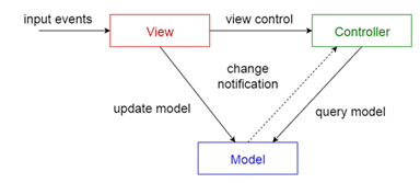
| MODEL-VIEW-CONTROLLER
(MVC) |
|
|
|
|
|
A system
may offer multiple user interfaces. Each user interface depicts all or part
of some application data. Changes to the data should be automatically and
flexibly reflected to all the different user interfaces. It should be also
possible to easily modify any one of the user interfaces, without affecting
the application logic associated with the data. The system is divided into
three different parts: a Model that encapsulates some application data and
the logic that manipulates that data, independently of the user interfaces;
one or multiple Views that display a specific portion of the data to the
user; a Controller associated with each View that receives user input and
translates it into a request to the Model. Views and Controllers constitute
the user interface. The users interact strictly through the Views and their
Controllers, independently of the Model, which in turn notifies all different
user interfaces about updates. |
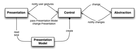
| PRESENTATION-ABSTRACTION-CONTROL
(PAC) |
|
|
|
|
|
An interactive system may offer multiple diverse functionalities
that need to be presented to the user through a coherent user interface. The
various functionalities may require their own custom user interface, and they
need to communicate with other functionalities in order to achieve a greater
goal. The users need not perceive this diversity but should interact with a
simple and consistent interface. The system is decomposed into a tree-like
hierarchy of agents: the leaves of the tree are agents that are responsible
for specific functionalities, usually assigned to a specific user interface;
at the middle layers there are agents that combine the functionalities of
related lower-level agents to offer greater services; at the top of the tree,
there is only one agent that orchestrates the middle-layer agents to offer
the collective functionality. Each agent is comprised of three parts: a
Presentation takes care of the user interface; an Abstraction maintains
application data and the logic that modifies it; a Control intermediates
between the Presentation and the Abstraction and handles all communication
with the Controls of other Agents. |
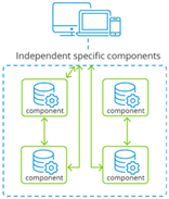
| Components
and Connectors (C2) |
|
|
|
|
|
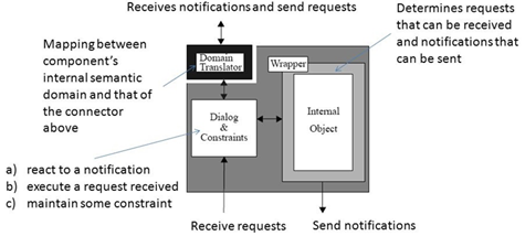
An interactive system is comprised of multiple components such
as GUI widgets, conceptual models of those widgets at various levels, data
structures, renderers, and of course application logic. The system may need
to support several requirements such as: different implementation language of
components, different GUI frameworks reused, distribution in a heterogeneous
network, concurrent interaction of components without shared address spaces,
run-time reconfiguration, multi-user interaction. Yet the system needs to be
designed to achieve separation of concerns and satisfy its performance
constraints. The system is decomposed into a top-to-bottom hierarchy of
concurrent componentsthat interactasynchronouslyby sending messages
throughexplicit connectors. Components submit request messages upwards in the
hierarchy, knowing the components above, but they send notification messages
downwards in the hierarchy, without knowing the components lying beneath.
Components are only connected with connectors, but connectors may be
connected to both components and other connectors. The purposes of connectors
is to broadcast, route, and filter messages. |
| Hierarchical Structure |
|
|
|
|
|
|
| CLIENT-SERVER |
|
|
|
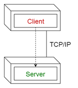
Two components need to communicate, and they are independent of
each other, even running in different processes or being distributed in
different machines. The two components are not equal peers communicating with
each other, but one of them is initiating the communication, asking for a
service that the other provides. Furthermore, multiple components might
request the same service provided by a single component. Thus, the component
providing a service must be able to cope with numerous requests at any time,
i.e. the component must scale well). On the other hand, the requesting
components using one and the same service might deal differently with the
results. This asymmetry between the components should be reflected in the
architecture for the optimization of quality attributes such as performance,
shared use of resources, and memory consumption. The CLIENT-SERVER pattern
distinguishes two kinds of components: clients and servers. The client
requests information or services from a server. To do so it needs to know how
to access the server, that is, it requires an ID or an address of the server
and of course the server’s interface. The server responds to the requests of
the client, and processes each client request on its own. It does not know
about the ID or address of the client before the interaction takes place.
Clients are optimized for their application task, whereas servers are
optimized for serving multiple clients. |
| PEER-TO-PEER |
|
|
|
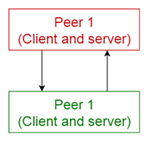
Consider a situation similar to that of a CLIENT-SERVER, but in
contrast to CLIENT-SERVER, there is no distinction between the components:
each component might both provide services and consume services. When a
component provides a service it must perform well according to the demands of
the requesting components. Each component must know how to access other
components. In the PEER-TO-PEER pattern each component has equal
responsibilities, in particular it may act both as a client and as a server.
Each component offers its own services (or data) and is able to access the
services in other components. The PEER-TO-PEER network consists of a dynamic
number of components. A PEER-TO-PEER component knows how to access the
network. Before a component can join a network, it must get an initial
reference to this network. This is solved by a bootstrapping mechanism, such
as providing public lists of dedicated peers or broadcast messages (using
IMPLICIT INVOCATION) in the network announcing peers. |
| MASTER-SLAVE |
|
|
|
|
|
The Master-slave pattern supportsfault toleranceandparallel
computation. The master component distributes the work among identical slave
components, and computes a final result from the results the slaves return.
The Master-slave pattern is applied for instance in process control, in
embedded systems, in large-scale parallel computations, and in fault-tolerant
systems. An application area for the Master-slave pattern is fault tolerance:
the master delegates the job to be done to several slaves, receives their
results, and applies a strategy to decide which result to return to the
client. One possible strategy is to choose the result from the first slave
that terminates. Another strategy is to choose the result that the majority
of slaves have computed. This is fail-proof with respect to slaves (the
master can provide a valid result as long as not all slaves fail), but not
with respect to the master. Failure of slaves may be detected by the master
using time-outs. Failure of the master means the system as a whole fails.
Another application area is parallel computing: the master divides a complex
task into a number of identical subtasks. An example is matrix computation:
each row in the product matrix can be computed by a separate slave. A third
application area is that of computational accuracy. The execution of a
service is delegated to different slaves, with at least three different
implementations. The master waits for the results, and applies a strategy for
choosing the best result (for instance the average, or the majority). The
Master-slave pattern is an example of the divide-and-conquer principle. In
this pattern, the aspect of coordination is separated from the actual work:
concerns are separated. The slaves are isolated: there is no shared state.
They operate in parallel. The latency in the master-slave communication can
be an issue, for instance in real-time systems: master and slaves live in
different processes. The pattern can only be applied to a problem that is
decomposable. |
| Message Passing
Mechanism |
|
|
|
|
|
|
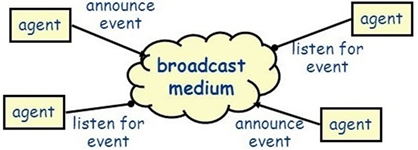
| PUBLISH-SUBSCRIBE |
|
|
|
|
|
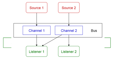
A component should be accessed or informed of a specific runtime
event. Events are of different nature than direct interactions as in
CLIENT-SERVER or PEER-TO-PEER. Sometimes a number of components should be
actively informed (an announcement or broadcast), in other cases only one
specific component is interested in the event. In contrast to EXPLICIT
INVOCATIONS, event producers and consumers need to be decoupled for a number
of reasons: to support locality of changes; to locate them in different
processes or machines; to allow for an arbitrary time period between the
announcement of interest in an event, and the actual triggering of the event.
Still, there must be a way to inform the interested components?
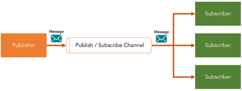
PUBLISH-SUBSCRIBE allows event consumers (subscribers) to register for
specific events, and event producers to publish (raise) specific events that
reach a specified number of consumers. The PUBLISH-SUBSCRIBE mechanism is
triggered by the event producers and automatically executes a callback-operation
to the event consumers. The mechanism thus takes care of decoupling producers
and consumers by transmitting events between them. |
| BROKER |
|
|
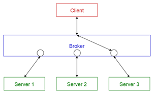
Distributed software system developers face many challenges that
do not arise in single-process software. One is the communication across
unreliable networks. Others are the integration of heterogeneous components
into coherent applications, as well as the efficient use of networking
resources. If developers of distributed systems must overcome all these
challenges within their application code, they may lose their primary focus:
to develop applications that efficiently tackle their domain-specific problems.
A BROKER separates the communication functionality of a distributed system
from its application functionality. The BROKER hides and mediates all
communication between the objects or components of a system. A BROKER
consists of a client-side REQUESTOR to construct and forward invocations, as
well as a server-side INVOKER that is responsible for invoking the operations
of the target remote object. A MARSHALLER on each side of the communication
path handles the transformation of requests and replies from
programminglanguage native data types into a byte array that can be sent over
the transmission medium. |
| REMOTE
PROCEDURE CALLS (RPC) |
|
|
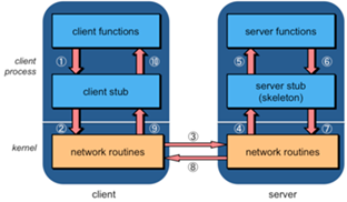
Consider the case where you want to realize an EXPLICIT
INVOCATION in a distributed setting. The use of low-level network protocols
requires developers to invoke the send and receive operations of the
respective network protocol implementations. This is undesirable because the
network access code cannot be reused, low-level details are not hidden, and
thus solutions are hard to maintain and understand. REMOTE PROCEDURE CALLS
extend the well-known procedure call abstraction to distributed systems. They
aim at letting a remote procedure invocation behave as if it were a local
invocation. Programs are allowed to invoke procedures (or operations) in a
different process and/or on a remote machine. |
| MESSAGE
QUEUING |
|
|
|
|
|
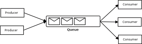
Consider a situation similar to that of REMOTE PROCEDURE CALLS,
but it is necessary to decouple the sender from the receiver to realize
queuing of invocations. Queuing is necessary, for instance, when temporal
outages of the receiver should be tolerated or when heterogeneous systems
should be integrated. For instance, when a legacy system using BATCH
SEQUENTIAL should be integrated into a distributed system, only one
invocation can be handled at a time by that system. Somewhere additional
messages must be queued until the system is ready to process the next
message. Messages are not passed from client to server application directly,
but through intermediate message queues that store and forward the messages.
This has a number of consequences: senders and receivers of messages are
decoupled, so they do not need to know each other’s location (perhaps not
even the identity). A sender just puts messages into a particular queue and
does not necessarily know who consumes the messages. For example, a message
might be consumed by more than one receiver. Receivers consume messages by
monitoring queues. |
| IMPLICIT
INVOCATION (EVENT-BASED) |
|
|
|
|
|
Consider the case where an invocation is needed, such as in
EXPLICIT INVOCATION. Furthermore, the client must be decoupled in various
ways from the supplier, during the delivery of the invocation and of the
result: the client might not know which supplier serves the invocation; or
the client may not initiate the invocation itself but is merely interested in
the invocation result; or the client does not need the result right away so
it can be occupied with another task in the meantime; or the supplier might
not be ready to reply to the client until some condition has been met; or
clients may be added or removed dynamically during the system runtime; or the
client does not know that the supplier is up and running and, if the supplier
is down, the system should suspend the invocation until the supplier is up
again; or the client and the supplier are part of dissimilar systems and thus
the invocation must be transformed, queued, or otherwise manipulated during
delivery. How can such additional requirements during delivery be met? In the
IMPLICIT INVOCATION pattern the invocation is not performed explicitly from
client to supplier, but indirectly and rather randomly through a special
mechanism such as PUBLISHSUBSCRIBE, MESSAGE QUEUING, or broadcast, that decouples
clients from suppliers. All additional requirements for invocation delivery
are handled by the IMPLICIT INVOCATION mechanism during the delivery of the
invocation. |
| EXPLICIT
INVOCATION |
|
|
|
Consider a component, the client, which needs to invoke a
service defined in another component, the supplier. Coupling the client with
the supplier in various ways is not only harmless but often desirable. For
example the client must know the exact network location of the component
which offers the service in order to improve performance; or the client must
always initiate the invocation itself; or the client must block, waiting for
the result of the invocation, before proceeding with its business; or the
topology of the interacting clients and suppliers is known beforehand and
must remain fixed. How can these two components interact? An EXPLICIT
INVOCATION allows a client to invoke services on a supplier, by coupling them
in various respects. The decisions that concern the coupling (e.g. network
location of the supplier) are known at design-time. The client provides these
design decisions together with the service name and parameters to the
EXPLICIT INVOCATION mechanism, when initiating the invocation. The EXPLICIT
INVOCATION mechanism performs the invocations and delivers the result to the
client as soon as it is computed. The EXPLICIT INVOCATION mechanism may be
part of the client and the server or may exist as an independent component. |
| Data Accessor |
|
|
|
|
|
|
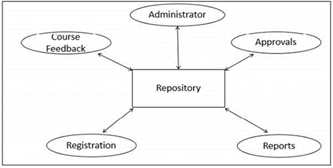
| SHARED REPOSITORY |
|
|
Data needs to be shared between components. In sequential
architectures like LAYERS or PIPES AND FILTERS the only way to share data
between the components (layers or filters) is to pass the information along
with the invocation, which might be inefficient for large data sets. Also it
might be inefficient, if the shared information varies from invocation to
invocation because the components’ interfaces must be prepared to transmit
various kinds of data. Finally the long-term persistence of the data requires
a centralized data management. In the SHARED REPOSITORY pattern one component
of the system is used as a central data store, accessed by all other
independent components. This SHARED REPOSITORY offers suitable means for
accessing the data, for instance, a query API or language. The SHARED
REPOSITORY must be scalable to meet the clients’ requirements, and it must
ensure data consistency. It must handle problems of resource contention, for
example by locking accessed data. The SHARED REPOSITORY might also introduce
transaction mechanisms. |
| ACTIVE
REPOSITORY |
|
|
|
|
|
A system needs to have a SHARED REPOSITORY, but it should not
just be passively accessed by accessor components. Clients need to be
immediately informed of specific events in the shared repository, such as
changes of data or access of data. “Polling” (i.e. querying in frequent
intervals) the SHARED REPOSITORY for such events does not work, for instance,
because this does not deliver timely information or inflicts overhead on the
system performance. An ACTIVE REPOSITORY is a SHARED REPOSITORY that is “active”
in the sense that it informs a number of subscribers of specific events that
happen in the shared repository. The ACTIVE REPOSITORY maintains a registry
of clients and informs them through appropriate notification mechanisms. |
| BLACKBOARD |
|
|
Consider the case where a SHARED REPOSITORY is needed for the
shared data of a computation, but no deterministic solution strategies are
known. Examples are image recognition or speech recognition applications.
However, it should be possible to realize a solution for these types of
applications. In a BLACKBOARD architecture the complex task is divided into
smaller sub-tasks for which deterministic solutions are known. The BLACKBOARD
is a SHARED REPOSITORY that uses the results of its clients for heuristic
computation and step-wise improvement of the solution. Each client can access
the BLACKBOARD to see if new inputs are presented for further processing and
to deliver results after processing. A control component monitors the
blackboard and coordinates the clients according to the state of the
blackboard. |
| System organization |
|
|
|
|
|
|
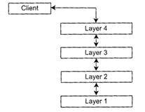
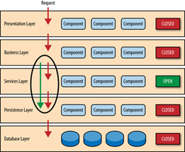
| LAYERS |
|
|
|
Consider a system in which high-level components depend on
low-level components to perform their functionality, which further depend on
even lower-level components and so on. Decoupling the components in a
vertical manner is crucial in order to support modifiability, portability,
and reusability. On the other hand components also require some horizontal
structuring that is orthogonal to their vertical subdivision. To achieve
these goals, the system is structured into LAYERS so that each layer provides
a set of services to the layer above and uses the services of the layer
below. Within each LAYER all constituent components work at the same level of
abstraction and can interact through connectors. Between two adjacent layers
a clearly defined interface is provided. In the pure form of the pattern,
layers should not be by-passed: higher-level layers access lower-level layers
only through the layer beneath. |
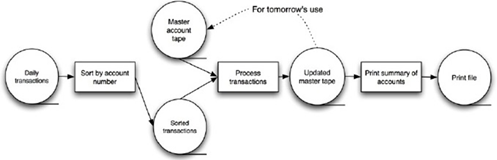
| BATCH
SEQUENTIAL |
|
|
|
|
|
Consider a complex task that can be sub-divided into a number of
smaller tasks, which can be defined as a series of independent computations.
This should not be realized by one monolithic component because this
component would be overly complex, and it would hinder modifiability and
reusability. In a BATCH SEQUENTIAL architecture the whole task is sub-divided
into small processing steps, which are realized as separate, independent
components. Each step runs to completion and then calls the next sequential
step until the whole task is fulfilled. During each step a batch of data is
processed and sent as a whole to the next step. |
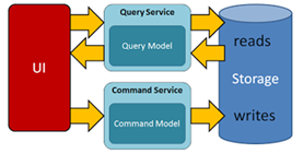
| CQRS |
|
|
|
|
|
Command and Query Responsibility Segregation (CQRS) is a pattern
that segregates the operations that read data (Queries) from the operations
that update data (Commands) by using separate interfaces. This implies that
the data models used for querying and updates are different. Compared to the
single model of the data (from which developers build their own conceptual
models) that is inherent in CRUD-based systems, the use of separate query and
update models for the data in CQRS-based systems considerably simplifies
design and implementation. However, one disadvantage is that, unlike CRUD
designs, CQRS code cannot automatically be generated by using scaffold
mechanisms. The query model for reading data and the update model for writing
data may access the same physical store, perhaps by using SQL views or by
generating projections on the fly. However, it is common to separate the data
into different physical stores to maximize performance, scalability, and
security; |
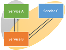
| SERVICE-ORIENTED
(SOA) |
|
|
|
In contrast to conventional software architectures primarily
delineating the organization of a system in its (sub)systems and their
interrelationships, the SOA captures a logical way of designing a software
system to provide services to either end-user applications or other services
distributed in a network through published and discoverable interfaces. SOA
is focused on creating a design style, technology, and process framework that
will allow enterprises to develop, interconnect, and maintain enterprise
applications and services efficiently and costeffectively.While this
objective is definitely not new, SOA seeks to eclipse previous efforts such
as modular programing, code reuse, and object-oriented software development
techniques. SOA requires that functions, or services, are defined by a
description language and have interfaces that perform useful business
processes. The fundamental intent of a service in an SOA is to represent a
reusable unit of business-complete work. A service in SOA is an exposed piece
of functionality with three essential properties. Firstly, an SOA-based
service is self-contained, i.e., the service maintains its own state.
Secondly, services are platform independent, implying that the interface
contract to the service is limited to platform independent assertions.
Lastly, the SOA assumes that services can be dynamically located, invoked and
(re-)combined. |
| MICROSERVICE |
|
|
A microservice is a software development technique—a variant of
the service-oriented architecture (SOA) architectural style that structures
an application as a collection of loosely coupled services. In a
microservices architecture, services are fine-grained and the protocols are
lightweight. The benefit of decomposing an application into different smaller
services is that it improves modularity and makes the application easier to
understand, develop, and test and more resilient to architecture erosion. It
parallelizes development by enabling small autonomous teams to develop,
deploy and scale their respective services independently. It also allows the
architecture of an individual service to emerge through continuous
refactoring. Microservices-based architectures enable continuous delivery and
deployment. |
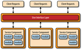
| COMPONENT-BASED
(CB) |
|
|
|
Component-based software engineering (CBSE), also called as
component-based development (CBD), is a branch of software engineering that
emphasizes the separation of concerns with respect to the wide-ranging
functionality available throughout a given software system. It is a
reuse-based approach to defining, implementing and composing loosely coupled
independent components into systems. This practice aims to bring about an
equally wide-ranging degree of benefits in both the short-term and the
long-term for the software itself and for organizations that sponsor such
software.
Software engineering practitioners regard components as part of the
starting platform for service-orientation. Components play this role, for
example, in web services, and more recently, in service-oriented
architectures (SOA), whereby a component is converted by the web service into
a service and subsequently inherits further characteristics beyond that of an
ordinary component. |
| SPACE-BASED
(CLOUD-BASED) |
|
|
|
|
|
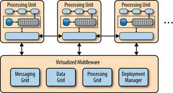
Space-based architecture (SBA) is a software architecture
pattern for achieving linear scalability of stateful, high-performance
applications using the tuple space paradigm. It follows many of the
principles of representational state transfer (REST), service-oriented
architecture (SOA) and event-driven architecture (EDA), as well as elements
of grid computing. With a space-based architecture, applications are built
out of a set of self-sufficient units, known as processing-units (PU). These
units are independent of each other, so that the application can scale by
adding more units. The SBA model is closely related to other patterns that
have been proved successful in addressing the application scalability
challenge, such as shared nothing architecture (SN), used by Google,
Amazon.com and other well-known companies. The model has also been applied by
many firms in the securities industry for implementing scalable electronic
securities trading applications. |
| PIPES
AND FILTERS |
|
|
|
|
|
Consider as in BATCH SEQUENTIAL the case where a complex task
can be sub-divided into a number of smaller tasks, which can be defined as a
series of independent computations. Additionally the application processes
streams of data, i.e. it transforms input data streams into output data
streams. This functionality should not be realized by one monolithic
component because this component would be overly complex, and it would hinder
modifiability and reusability. Furthermore, different clients require different
variations of the computations, for instance, the results should be presented
in different ways or different kinds of input data should be provided. To
reach this goal, it must be possible to flexibly compose individual sub-tasks
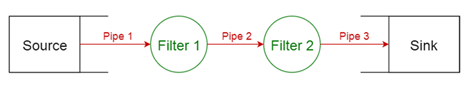
according to the client’s demands. In a PIPES AND FILTERS architecture a
complex task is divided into several sequential subtasks. Each of these
sub-tasks is implemented by a separate, independent component, a filter,
which handles only this task. Filters have a number of inputs and a number of
outputs and they are connected flexibly using pipes but they are never aware
of the identity of adjacent filters. Each pipe realizes a stream of data
between two components. Each filter consumes and delivers data incrementally,
which maximizes the throughput of each individual filter, since filters can
potentially work in parallel. Pipes act as data buffers between adjacent
filters. The use of PIPES AND FILTERS is advisable when little contextual
information needs to be maintained between the filter components and filters
retain no state between invocations. PIPES AND FILTERS can be flexibly
composed. However, sharing data between these components is expensive or
inflexible. There are performance overheads for transferring data in pipes
and data transformations, and error handling is rather difficult. |
| Business Logic |
|
|
|
|
|
|
| RULE-BASED SYSTEM |
|
|
|
|
|
Logical problems are hard to express elegantly in imperative
languages that are typically used in INTERPRETERS and VIRTUAL MACHINES.
Consider for instance an expert system that provides the knowledge of an
expert or a set of constraints. In imperative languages these are expressed
by nested if-statements or similar constructs which are rather hard to
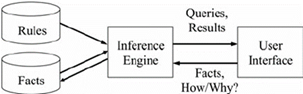
understand. A RULE-BASED SYSTEM offers an alternative for expressing such
problems in a system. It consists mainly of three things: facts, rules, and
an engine that acts on them. Rules represent knowledge in form of a condition
and associated actions. Facts represent data. A RULE-BASED SYSTEM applies its
rules to the known facts. The actions of a rule might assert new facts,
which, in turn, trigger other rules. |
| INTERPRETER |
|
|
|
|
|
A language syntax and grammar needs to be parsed and interpreted
within an application. The language needs to be interpreted at runtime (i.e.
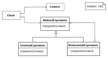
using a compiler is not feasible). An INTERPRETER for the language is
provided, which provides both parsing facilities and an execution
environment. The program that needs to be interpreted is provided in form of
scripts which are interpreted at runtime. These scripts are portable to each
platform realization of the INTERPRETER. For instance, the INTERPRETER can define
a class per grammar rule of the language. The parser of the interpreter
parses language instructions according to these rules and invokes the
interpretation classes. Many more complex INTERPRETER architectures exist. |
| Dynamic component |
|
|
|
|
|
|
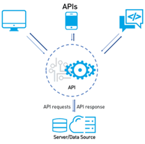
| INDIRECTION LAYER |
|
|
|
|
|
A sub-system should be accessed by one or more components, but
direct access to the subsystem is problematic. For instance, the components
should not get hard-wired into the subsystem, instead the accessors for the
sub-system should be reused. Or the access should be defined in a way that it
can be flexibly adapted to changes. The same problem appears at different
levels of scale: it can happen between two ordinary components in one
environment, components in two different languages, components in two different
systems (e.g. if a legacy system is accessed). An INDIRECTION LAYER is a
LAYER between the accessing component and the “instructions” of the
sub-system that needs to be accessed. The general term “instructions” can
refer to a whole programming language, or an application programming
interface (API) or the public interface(s) of a component or sub-system, or
other conventions that accessing components must follow. The INDIRECTION
LAYER wraps all accesses to the relevant sub-system and should not be
bypassed. The INDIRECTION LAYER can perform additional tasks while deviating
invocations to the subsystem, such as converting or tracing the invocations. |
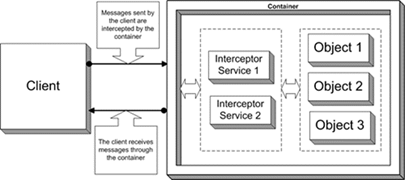
| INTERCEPTOR |
|
|
|
|
|
A framework offers a number of reusable services to the
applications that extend it. These services need to be updated in the future
as the application domain matures and they should still be offered by the
framework, so that the application developers do not need to re-implement
them. Furthermore, the framework developer cannot predict all such future
services at the point of time where the framework is created, while
application developers may not be able to add unanticipated extensions to the
framework, in case e.g. that the framework is a black-box. An INTERCEPTOR is
a mechanism for transparently updating the services offered by the framework
in response to incoming events. An application can register with the
framework any number of INTERCEPTORS that implement new services. The
framework facilitates this registration through dispatchers that assign
events to INTERCEPTORS. The framework also provides the applications with the
means to introspect on the framework’s behavior in order to properly handle
the events. |
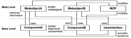
| REFLECTION |
|
|
|
|
|
Software systems constantly evolve and change over the time, and
unanticipated changes are often required. It is hard to automatically cope
with changes that are not foreseen. In a REFLECTION architecture all
structural and behavioral aspects of a system are stored into meta-objects
and separated from the application logic components. The latter can query the
former (that may have changed at any point of time) in order to execute their
functionality. Thus REFLECTION allows a system to be defined in a way that
allows for coping with unforeseen situations automatically. |
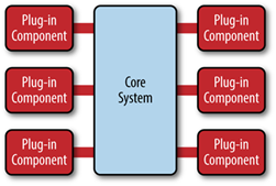
| MICROKERNEL |
|
|
|
Consider a system family where different versions of a system
need to be supported. In each version, components can be composed in
different ways and other details, such as the offered services, public APIs,
or user interfaces, might be different. Nonetheless, the system family should
be realized using a common architecture to ease software maintenance and
foster reuse. A MICROKERNEL realizes services that all systems, derived from
the system family, need and a plug-and-play infrastructure for the system-specific
services. Internal servers (not visible to clients) are used to realize
version-specific services and they are only accessed through the MICROKERNEL.
On the other hand, external servers offer APIs and user interfaces to clients
by using the MICROKERNEL. External servers are the only way for clients to
access the MICROKERNEL architecture. |
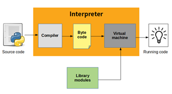
| VIRTUAL
MACHINE |
|
|
|
|
|
An
efficient execution environment for a programming language is needed. The
architecture should facilitate portability, code optimizations, and native
machine code generation. Runtime interpretation of the language is not
necessarily required. A VIRTUAL MACHINE defines a simple machine architecture
on which not machine code but an intermediate form called the byte-code can
be executed. The language is compiled into that byte-code. The VIRTUAL
MACHINE can be realized on different platforms, so that the byte-code can be
portable between these platforms. The VIRTUAL MACHINE redirects invocations
from a byte-code layer into an implementation layer for the commands of the
byte-code. |
| |
|
|
|
|
|
|
|
|
|
|
|
|
|